Getting Started with ASP.NET Core Diagram Control
25 May 20269 minutes to read
This section explains the steps required to create a simple diagram and demonstrates the basic usage of the ASP.NET Core Diagram control.
Ready to streamline your Syncfusion® ASP.NET Core development? Discover the full potential of Syncfusion® ASP.NET Core controls with Syncfusion® AI Coding Assistant. Effortlessly integrate, configure, and enhance your projects with intelligent, context-aware code suggestions, streamlined setups, and real-time insights—all seamlessly integrated into your preferred AI-powered IDEs like Visual Studio, Visual Studio Code, Cursor, Syncfusion® CodeStudio and more. Explore Syncfusion® AI Coding Assistant
Prerequisites
Before getting started, ensure that your development environment meets the system requirements for Syncfusion® ASP.NET Core controls.
Before You Begin
This guide uses the Razor Pages application structure generated by the latest .NET SDK.
The main files used in this guide are:
-
~/Pages/_ViewImports.cshtml— Imports the Syncfusion® tag helpers. -
~/Pages/Shared/_Layout.cshtml— Contains shared layout, style, and script references. -
~/Pages/Index.cshtml— Hosts the Diagram control. -
~/Pages/Index.cshtml.cs— Defines the nodes and connectors data passed to the view.
NOTE
If your application uses the MVC pattern instead of Razor Pages, the equivalent files are typically ~/Views/_ViewImports.cshtml, ~/Views/Shared/_Layout.cshtml, ~/Views/Home/Index.cshtml, and ~/Controllers/HomeController.cs.
Step 1: Create an ASP.NET Core web application
Create a new ASP.NET Core Razor Pages application using Visual Studio or the .NET CLI.
Using the .NET CLI:
dotnet new webapp -n MyDiagramApp
Navigate to the project folder:
cd MyDiagramApp
NOTE
You can also create a project using Microsoft templates or the Syncfusion® ASP.NET Core Extension in Visual Studio.
Step 2: Install the Syncfusion® ASP.NET Core Diagram package
All Syncfusion® ASP.NET Core packages are available on nuget.org.
Install the Syncfusion.EJ2.AspNet.Core NuGet package using the Package Manager Console:
Install-Package Syncfusion.EJ2.AspNet.Core -Version 34.1.29
Or using the .NET CLI:
dotnet add package Syncfusion.EJ2.AspNet.Core
NOTE
The
Syncfusion.EJ2.AspNet.Corepackage automatically installs its required dependencies, including Newtonsoft.Json and Syncfusion.Licensing.
Step 3: Register the Syncfusion® Tag Helper
Open the ~/Pages/_ViewImports.cshtml file and add the Syncfusion® tag helper reference.
@addTagHelper *, Syncfusion.EJ2
This makes the <ejs-*> tag helpers, including <ejs-diagram>, available in all Razor pages.
Step 4: Add the required style and script references
Add the Syncfusion® theme and script references inside the <head> of the ~/Pages/Shared/_Layout.cshtml file along with the existing content.
<head>
    ...
    <!-- Syncfusion® ASP.NET Core controls styles -->
    <link rel="stylesheet" href="https://cdn.syncfusion.com/ej2/34.1.29/tailwind3.css" />
    <!-- Syncfusion® ASP.NET Core controls scripts -->
    <script src="https://cdn.syncfusion.com/ej2/34.1.29/dist/ej2.min.js"></script>
</head>
NOTE
Syncfusion® provides multiple built-in themes. To use a different theme, replace tailwind3.css with the corresponding theme file, such as material3.css or fluent.css. See the Themes topic for more details.
NOTE
Refer to the Adding Script Reference topic to learn other approaches such as NPM and CRG for adding script references.
Step 5: Register the Syncfusion® Script Manager
Add the <ejs-scripts> tag at the end of the <body> in the ~/Pages/Shared/_Layout.cshtml file. The script manager renders the scripts required for Syncfusion® controls to function correctly.
<body>
    ...
    <!-- Syncfusion® ASP.NET Core Script Manager -->
    <ejs-scripts></ejs-scripts>
</body>
Step 6: Add the Diagram control
Add the <ejs-diagram> tag helper to the ~/Pages/Index.cshtml file.
@page
@model IndexModel
<ejs-diagram id="diagram" width="100%" height="580px"></ejs-diagram>
This renders an empty diagram in the application.
NOTE
The Diagram control must have a valid height. If the height is not set, the Diagram canvas may not be visible.
Create your first Diagram with nodes and connectors
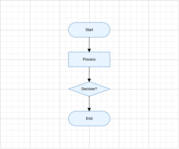
This section explains how to create a simple flowchart by adding nodes, customizing their appearance, and connecting them using connectors.
The following example creates a flowchart with four nodes: Start, Process, Decision, and End. Nodes and connectors are defined in Index.cshtml.cs and passed to the view through ViewBag. The view then binds them to the <ejs-diagram> tag helper.
Define nodes and connectors
Open ~/Pages/Index.cshtml.cs and declare nodes and connectors as public properties on the page model. Populate them inside the OnGet method so they are available to the view when the page loads.
using Microsoft.AspNetCore.Mvc.RazorPages;
using Syncfusion.EJ2.Diagrams;
using System.Collections.Generic;

public class IndexModel : PageModel
{
    public List<DiagramNode> nodes { get; set; }
    public List<DiagramConnector> connectors { get; set; }

    public void OnGet()
    {
        // Define nodes
        nodes = new List<DiagramNode>()
        {
            new DiagramNode()
            {
                Id = "node1", OffsetX = 300, OffsetY = 100,
                Shape = new { type = "Flow", shape = "Terminator" },
                Annotations = new List<DiagramNodeAnnotation>()
                {
                    new DiagramNodeAnnotation() { Content = "Start" }
                }
            },
            new DiagramNode()
            {
                Id = "node2", OffsetX = 300, OffsetY = 200,
                Shape = new { type = "Flow", shape = "Process" },
                Annotations = new List<DiagramNodeAnnotation>()
                {
                    new DiagramNodeAnnotation() { Content = "Process" }
                }
            },
            new DiagramNode()
            {
                Id = "node3", OffsetX = 300, OffsetY = 300,
                Shape = new { type = "Flow", shape = "Decision" },
                Annotations = new List<DiagramNodeAnnotation>()
                {
                    new DiagramNodeAnnotation() { Content = "Decision?" }
                }
            },
            new DiagramNode()
            {
                Id = "node4", OffsetX = 300, OffsetY = 400,
                Shape = new { type = "Flow", shape = "Terminator" },
                Annotations = new List<DiagramNodeAnnotation>()
                {
                    new DiagramNodeAnnotation() { Content = "End" }
                }
            }
        };

        // Define connectors
        connectors = new List<DiagramConnector>()
        {
            new DiagramConnector() { Id = "connector1", SourceID = "node1", TargetID = "node2" },
            new DiagramConnector() { Id = "connector2", SourceID = "node2", TargetID = "node3" },
            new DiagramConnector() { Id = "connector3", SourceID = "node3", TargetID = "node4" }
        };
    }
}
Bind the data
Update ~/Pages/Index.cshtml to bind @Model.nodes and @Model.connectors to the <ejs-diagram> tag helper. The JavaScript function names are passed as string variables using the Razor @{ } block.
@page
@model IndexModel
@{
    var getNodeDefaults = "getNodeDefaults";
    var getConnectorDefaults = "getConnectorDefaults";
}

<ejs-diagram id="diagram" width="100%" height="580px"
             nodes="@Model.nodes"
             connectors="@Model.connectors"
             getNodeDefaults="getNodeDefaults"
             getConnectorDefaults="getConnectorDefaults">
</ejs-diagram>

<script>
    function getNodeDefaults(node) {
        node.width = 140;
        node.height = 50;
        node.style = {
            fill: '#E8F4FF',
            strokeColor: '#357BD2'
        };
        return node;
    }

    function getConnectorDefaults(connector) {
        connector.type = 'Orthogonal';
        connector.targetDecorator = {
            shape: 'Arrow',
            width: 10,
            height: 10
        };
        return connector;
    }
</script>
In this example:
-
nodesandconnectorsare public properties onIndexModel, populated inOnGet()and accessed in the view via@Model. -
OffsetXandOffsetYdefine the position of each node. -
Shapesets the flowchart shape type, such asTerminator,Process, orDecision. -
Annotationsadds a text label inside each node using theContentproperty. -
SourceIDandTargetIDconnect one node to another. -
getNodeDefaultsapplies common width, height, fill color, and stroke color to all nodes. -
getConnectorDefaultsapplies common connector settings such as orthogonal routing and target arrows.
Step 7: Run the application
Run the application using the following command:
dotnet run
Alternatively, press Ctrl+F5 (Windows) or ⌘+F5 (macOS) in Visual Studio.
Open the generated local URL in the browser. The application displays the flowchart with four connected nodes.
The output will appear as follows:
NOTE