Ports in Diagram Control
19 Jun 202524 minutes to read
Diagram provides support to define custom ports for making connections.
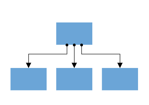
When a connector is connected between two nodes, its end points are automatically docked to the node’s nearest boundary.
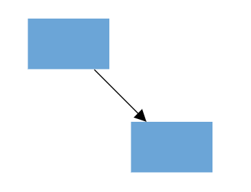
Ports act as the connection points of the node and allows to create connections with only those specific points.
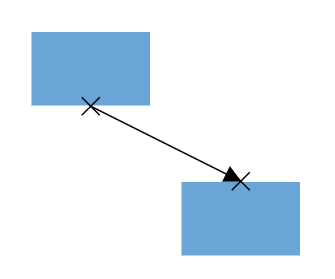
Create port
Add ports when initializing nodes
To add a connection port, define the port object and add it to node’s ports collection. The offset property of port accepts an object of fractions and used to determine the position of ports.
using System;
using System.Collections.Generic;
using System.Linq;
using System.Web;
using System.Web.Mvc;
using Syncfusion.EJ2.Diagrams;
using System.Drawing;

namespace EJ2MVCSampleBrowser.Controllers.Diagram {
    public partial class DiagramController: Controller {
        // GET: Nodes
        public ActionResult Nodes() {

            List < DiagramPort > ports1 = new List < DiagramPort > ();
            ports1.Add(new CustomPort() {
                Id = "port1", Shape = PortShapes.Circle,
                    Offset = new DiagramPoint() {
                        X = 0.5, Y = 0.5
                    }
            });
            List < DiagramNode > nodes = new List < DiagramNode > ();
            nodes.Add(new Node() {
                Id = "node1",
                    Width = 100,
                    Height = 100,
                    Style = new NodeStyleNodes() {
                        Fill = "#6BA5D7",
                        StrokeColor = "White"
                    },
                    text = "node1",
                    OffsetX = 100,
                    OffsetY = 100,
                    Ports = ports1
            });
            ViewBag.nodes = nodes;


            return View();
        }
    }
    public class Node: DiagramNode {
        public string text;
    }
}
Add ports at runtime
Add ports at runtime by using the client-side method addPorts.
The port’s ID property is used to define the unique ID for the port and its further used to find the port at runtime. If ID is not set, then default ID is automatically set.
using System;
using System.Collections.Generic;
using System.Linq;
using System.Web;
using System.Web.Mvc;
using Syncfusion.EJ2.Diagrams;
using System.Drawing;

namespace EJ2MVCSampleBrowser.Controllers.Diagram {
    public partial class DiagramController: Controller {
        // GET: Nodes
        public ActionResult Nodes() {
            List < DiagramNode > nodes = new List < DiagramNode > ();
            nodes.Add(new Node() {
                Id = "node1",
                    Width = 100,
                    Height = 100,
                    Style = new NodeStyleNodes() {
                        Fill = "#6BA5D7",
                        StrokeColor = "White"
                    },
                    text = "node1",
                    OffsetX = 100,
                    OffsetY = 100,
            });
            ViewBag.nodes = nodes;


            return View();
        }
    }
    public class Node: DiagramNode {
        public string text;
    }
}
// Initialize port collection
var port= [{
id: 'port1',
offset: {
x: 0,
y: 0.5
},
visibility: PortVisibility.Visible
} {
id: 'port2',
offset: {
x: 1,
y: 0.5
},
visibility: PortVisibility.Visible
},
{
id: 'port3',
offset: {
x: 0.5,
y: 0
},
visibility: PortVisibility.Visible
},
{
id: 'port4',
offset: {
x: 0.5,
y: 1
},
visibility: PortVisibility.Visible
}
];
// Method to add ports through run time
diagram.addPorts(diagram.nodes[0], port);Remove ports at runtime
Remove ports at runtime by using client-side method removePorts.
using System;
using System.Collections.Generic;
using System.Linq;
using System.Web;
using System.Web.Mvc;
using Syncfusion.EJ2.Diagrams;
using System.Drawing;

namespace EJ2MVCSampleBrowser.Controllers.Diagram {
    public partial class DiagramController: Controller {
        // GET: Nodes
        public ActionResult Nodes() {
            List < DiagramPort > ports1 = new List < DiagramPort > ();
            ports1.Add(new CustomPort() {
                Id = "port1", Shape = PortShapes.Circle, Offset = new DiagramPoint() {
                    X = 0, Y = 0.5
                }, Visibility = PortVisibility.Visible
            });
            ports1.Add(new CustomPort() {
                Id = "port2", Shape = PortShapes.Circle, Offset = new DiagramPoint() {
                    X = 1, Y = 0.5
                }, Visibility = PortVisibility.Visible
            });
            ports1.Add(new CustomPort() {
                Id = "port3", Shape = PortShapes.Circle, Offset = new DiagramPoint() {
                    X = 0.5, Y = 1
                }, Visibility = PortVisibility.Visible
            });
            ports1.Add(new CustomPort() {
                Id = "port4", Shape = PortShapes.Circle, Offset = new DiagramPoint() {
                    X = 1, Y = 1
                }, Visibility = PortVisibility.Visible
            });

            List < DiagramNode > nodes = new List < DiagramNode > ();
            nodes.Add(new Node() {
                Id = "node1",
                    Width = 100,
                    Height = 100,
                    Style = new NodeStyleNodes() {
                        Fill = "#6BA5D7",
                            StrokeColor = "White"
                    },
                    text = "node1",
                    OffsetX = 100,
                    OffsetY = 100,
                    Ports = ports1
            });
            ViewBag.nodes = nodes;


            return View();
        }
    }
    public class Node: DiagramNode {
        public string text;
    }
}
var ports = [{
id: 'port1',
}, {
id: 'port2',
}, {
id: 'port3',
}, {
id: 'port4',
}]
diagram.removePorts(diagram.nodes[0], ports);Update port at runtime
You can change any port properties at runtime and update it through the client-side method dataBind.
using System;
using System.Collections.Generic;
using System.Linq;
using System.Web;
using System.Web.Mvc;
using Syncfusion.EJ2.Diagrams;
using System.Drawing;

namespace EJ2MVCSampleBrowser.Controllers.Diagram {
    public partial class DiagramController: Controller {
        // GET: Nodes
        public ActionResult Nodes() {

            List < DiagramPort > ports1 = new List < DiagramPort > ();
            ports1.Add(new CustomPort() {
                Id = "port1", Shape = PortShapes.Circle,
                    Offset = new DiagramPoint() {
                        X = 0.5, Y = 0.5
                    }
            });
            List < DiagramNode > nodes = new List < DiagramNode > ();
            nodes.Add(new Node() {
                Id = "node1",
                    Width = 100,
                    Height = 100,
                    Style = new NodeStyleNodes() {
                        Fill = "#6BA5D7",
                        StrokeColor = "White"
                    },
                    text = "node1",
                    OffsetX = 100,
                    OffsetY = 100,
                    Ports = ports1
            });
            ViewBag.nodes = nodes;


            return View();
        }
    }
    public class Node: DiagramNode {
        public string text;
    }
}diagram.nodes[0].ports[0].offset = {
x: 1,
y: 1
};
diagram.dataBind();Appearance
-
The shape of port can be changed by using its shape property. To explore the different types of port shapes, refer to Port Shapes. If you need to render a custom shape, then you can set shape as path and define path using path data property of port.
-
The appearance of ports can be customized by using
strokeColor,strokeWidth, andfillproperties of the port. -
Customize the port size by using the
widthandheightproperties of port. -
The ports
visibilityproperty allows to define, when the port should be visible.
using System;
using System.Collections.Generic;
using System.Linq;
using System.Web;
using System.Web.Mvc;
using Syncfusion.EJ2.Diagrams;
using System.Drawing;

namespace EJ2MVCSampleBrowser.Controllers.Diagram {
    public partial class DiagramController: Controller {
        // GET: Nodes
        public ActionResult Nodes() {

            List < DiagramPort > ports1 = new List < DiagramPort > ();
            ports1.Add(new CustomPort() {
                Id = "port1", Shape = PortShapes.Circle,
                    Offset = new DiagramPoint() {
                        X = 0.5, Y = 0.5
                    },
                    style = new DiagramShapeStyle() {
                        Fill = "Black", StrokeColor = "Red", StrokeWidth = 2
                    },
                    Visibility = PortVisibility.Visible
            });
            List < DiagramNode > nodes = new List < DiagramNode > ();
            nodes.Add(new Node() {
                Id = "node1",
                    Width = 100,
                    Height = 100,
                    Style = new NodeStyleNodes() {
                        Fill = "#6BA5D7",
                            StrokeColor = "White"
                    },
                    text = "node1",
                    OffsetX = 100,
                    OffsetY = 100,
                    Ports = ports1
            });
            ViewBag.nodes = nodes;


            return View();
        }
    }
    public class Node: DiagramNode {
        public string text;
    }
}
Offset
The offset property of port is used to align the port based on fractions. 0 represents top/left corner, 1 represents bottom/right corner, and 0.5 represents half of width/height.
Constraints
The constraints property allows to enable/disable certain behaviors of ports. For more information about port constraints, refer to Port Constraints.
Specify connection direction to port
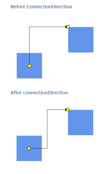
The connectionDirection property of a port allows users to specify the direction in which a connector should establish a connection. This can be either to the port (incoming) or from the port (outgoing).
var port= [{
        id: 'port1',
        offset: {
            x: 0,
            y: 0.5
        },
        //specify the connectionDirection of the Port
        connectionDirection:'Right'
    } {
        id: 'port2',
        offset: {
            x: 1,
            y: 0.5
        },
        //specify the connectionDirection of the Port
        connectionDirection:'Left'
    },

];
Automatic Port Creation
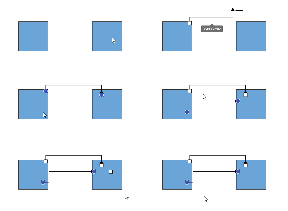
The Diagram component allows you to dynamically create ports on nodes or connectors by clicking and dragging the mouse while holding the Control (Ctrl) key. This feature is disabled by default and can be enabled by using the DiagramConstraints.AutomaticPortCreation constraint.
You can also remove a port using the same Ctrl + Click interaction, but only if the port is not currently connected to any connector.
The following example shows how to enable automatic port creation:
@Syncfusion.EJ2.Diagrams;

@(Html.EJS().Diagram("container").Width("100%").Height("500px")
    .SnapSettings(s => s.Constraints(SnapConstraints.None))
    .Nodes((List<DiagramNode>)ViewData["nodes"])
    .Constraints(DiagramConstraints.Default | DiagramConstraints.AutomaticPortCreation).Render()
)
using System;
using System.Collections.Generic;
using System.Web.Mvc;
using Syncfusion.EJ2.Diagrams;
namespace EJ2MVCSampleBrowser.Controllers.Diagram
{
public partial class DiagramController : Controller
{
public ActionResult AutoPort()
{
List<DiagramNode> nodes = new List<DiagramNode>();
nodes.Add(new Node()
{
Id = "node1",
Width = 100,
Height = 100,
Style = new NodeStyleNodes()
{
Fill = "cornflowerblue",
},
text = "node1",
OffsetX = 150,
OffsetY = 200,
Constraints = NodeConstraints.Default & ~(NodeConstraints.InConnect | NodeConstraints.OutConnect)
});
nodes.Add(new Node()
{
Id = "node2",
Width = 100,
Height = 100,
Style = new NodeStyleNodes()
{
Fill = "cornflowerblue",
},
text = "node2",
OffsetX = 400,
OffsetY = 200,
Constraints = NodeConstraints.Default & ~(NodeConstraints.InConnect | NodeConstraints.OutConnect)
});
ViewData.nodes = nodes;
return View();
}
}
public class Node : DiagramNode
{
public string text;
}
}